
01 / Drawing detail
Working geometry
Identify every working diameter, step, taper, shoulder and tip profile. Give the working length and overall length, and dimension transitions that matter to the application.
Products / U.S. Core Pins Inc.
Custom core pins and precision pins made in the USA to your drawings. Source components for new molds, replacement tooling and production requirements from U.S. Core Pins in Santa Ana, California.
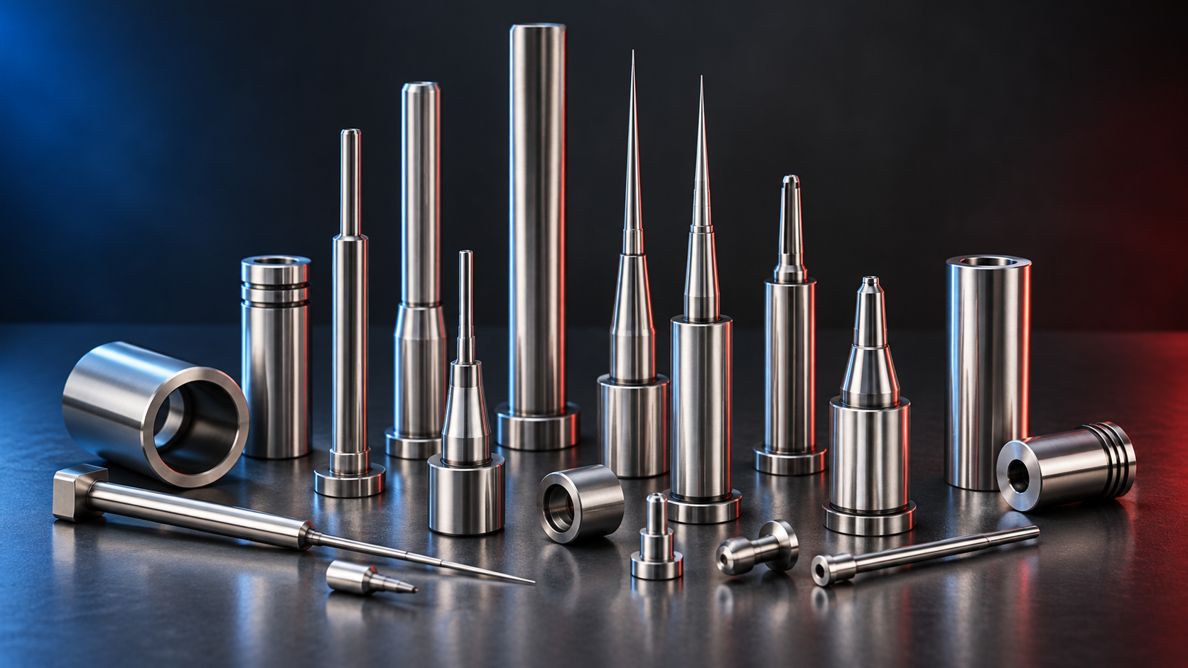
Your component / Your application
A core pin occupies space within a mold to form a hole or internal feature in the molded part. Its working profile, location and surface condition therefore matter to the feature being produced.
Whether you are specifying a new pin or sourcing a replacement, the complete component drawing connects the quote to your tooling requirements. Include locating and retention features alongside the working end so the quote covers the finished part.
01 / Drawing detail
Identify every working diameter, step, taper, shoulder and tip profile. Give the working length and overall length, and dimension transitions that matter to the application.
02 / Drawing detail
Define the surfaces that locate the pin in the tool and the required mating fits. Show applicable datums and geometric controls on the drawing instead of relying on a description such as “tight tolerance.”
03 / Drawing detail
Specify the material grade, required condition and finish where known. Identify which surfaces form the molded feature and whether dimensions apply before or after any specified treatment.
Ready for pricing
Send your drawing, quantity and desired delivery date. Add the requirements you have available. If something is undecided, our sales team can discuss it with you.
Your quote confirms the manufacturing scope, pricing and delivery timing.
Common questions
Their functions differ: a core pin forms a feature, while an ejector pin applies force to release a molded part. Dimensions, mounting and material requirements must match the tooling design; similar appearance alone does not establish interchangeability.
Start with the current component drawing. Mark the features that control fit or function, include any mating information needed for review, and identify unresolved requirements. The team will confirm the scope and feasibility in the quote.
Your next component
Upload your PDF drawing, quantity and desired delivery date. Have questions first, or need to send native CAD files? Contact sales directly.